Keywords: Intermediate axis theorem, Tennis racket theorem, Dzhanibekov effect, Coriolis force, Euler equations
In 1988 I witnesses the instability of the rotation about the intermediate axis of a foam brick.
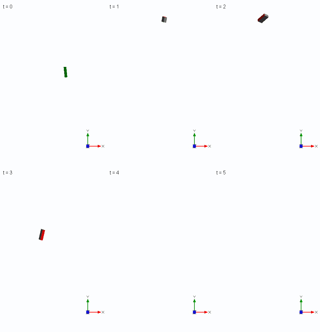
Since then I have been fascinated by this effect. It was one of the many experiments which enriched a lecture series on kinetics and on that day Euler equations were on the agenda. Colored surfaces of the brick made it possible to observe the effect without micro gravity and slow-motion equipment.
This post is about reproducing an “intuitive” visualization of an explanation of the effect by Terry Tao from 2011 using 4 rigidly connected point masses. 8 years later the explanation was animated in a YouTube video (The Bizarre Behavior of Rotating Bodies) and considered to be the “best intuitive” explanation.
Motivated by the video, I wondered whether a similar animation with acting forces is possible with MapleSoft products and whether there might be a better intuitive explanation without the use of centrifugal forces. Initially I saw this more as a good test of MapleSim’s visualization capabilities. Finally, it took over 3 years and numerous attempts (mostly during vacation, kind of a substitute for drawing circles in the sand...) to come to a conclusion on the effect.
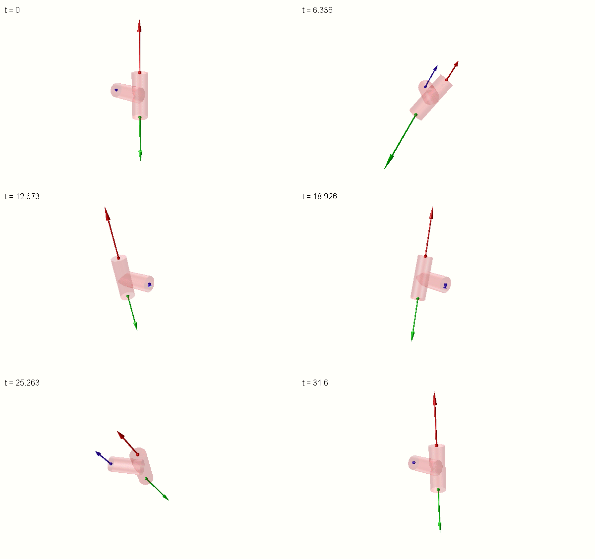
Intermediate_axis_theoreme_with_3_point_masses.msim
About the model:
Unlike the YouTube video, I decided to simulate 3 identical point masses because a 3-mass model fits better to a T-handle (overlayed in the animation above), video footage from space experiments and discussions in this forum (221298, 225760, 228066).
The movement of the model generates acceleration forces on each mass. The clip displays the corresponding opposing forces that act in the model (i.e. act on the massless T-structure). The blue mass, which is not perfectly centered on the axis of rotation at the start of the simulation perturbs the orbits of the red and the green masses. That was my initial intuitive attempt to explain the effect.
The 3 masses form an isosceles triangle. Here it is helpful to think of a rotating arrowhead where the shape determines stability of the rotation. The aspect ratio (the ratio of the height to the base length) of the triangle determines the stability of rotation about the mirror symmetry axis of the triangle (i.e. the symmetry axis of the T-structure). An obtuse triangle (“blunt”, aspect ratio < sqrt(3)/2) is unstable when rotating about an axis that is slightly inclined with respect to this axis of symmetry. The inclination can be in the plane of the triangle or out of plane. An acute (“pointy”) triangle only wobbles.
About the MapleSim model:
A supplementary rigid body component without mass and rotational inertia is used at the center of mass of the three masses to impose initial conditions. Rotating the triangle at the start of the simulation about the center of mass of the 3 masses prevents the triangle from drifting laterally away from its initial position. This effect of lateral drift is visible in video footage from space with the T-handle.
The rotational inertia of the other rigid body components is set to zero. Without rotational inertia it could be assumed that only Newtonian mechanics are used in the simulation (i.e. no Euler equations are integrated). This is however wrong. MapleSim generates automatically from a system with 3x6=18 coordinates a system with 3 Newtonian equations for translation and 3 Euler equations for rotation.
Forces and moments are measured with sensor components. Visualization is done with force and moment visualization components. These components are “abused” to display the following other physical quantities:
The angular momentum of the masses
The vectors of the angular velocity and the angular acceleration
Moments of the forces with respect to the center of mass
Moments of the forces with respect to the center of the base of the triangle
For a clean model, sensor components and mathematical components to calculate physical quantities are grouped in three subsystems (one per mass, indicated with a colored dot in the image below).
The model contains parameter sets for in plane and out of plane inclination of the axis of the T with respect to the initial axis of rotation (the x-axis).

Visualization of physical components can be turned on by enabling the corresponding subsystems which are labeled accordingly (in the image above the display of the angular momentum is enabled). The subsystem “Verification” computes quantities that should either be conserved or should be equal to zero. Calculation of quantities is done with MapleSim’s mathematical components (i.e. no embedded code or custom components are used).
Some observations
Kinetic energies are exchanged between the masses. During a flip of the T (see animation above), the red and green masses “exchange” their energy. The blue mass mediates this exchange. Depending on the initial conditions (in plane or out of plane), the energy of the red mass decreases first during the flip and the energy of the green mass increases (and vice versa, as seen below for the out of plane case which exhibits symmetric energy distributions).
Energy peaks are a good measure for the flip frequency. The frequency increases with the initial misalignment of the rotation axis to the symmetry axis of the T.

Tracing the blue perturbing mass reveals that the mass never gets closer to the (initial) rotation axis than its initial off-axis position.

The angular momenta of the masses vary, but the total angular momentum is, as expected, conserved. In the image below the angular momenta of the three masses are visualized to the left. The change of kinetic energy can be appreciated from the change in magnitude of the angular momenta.
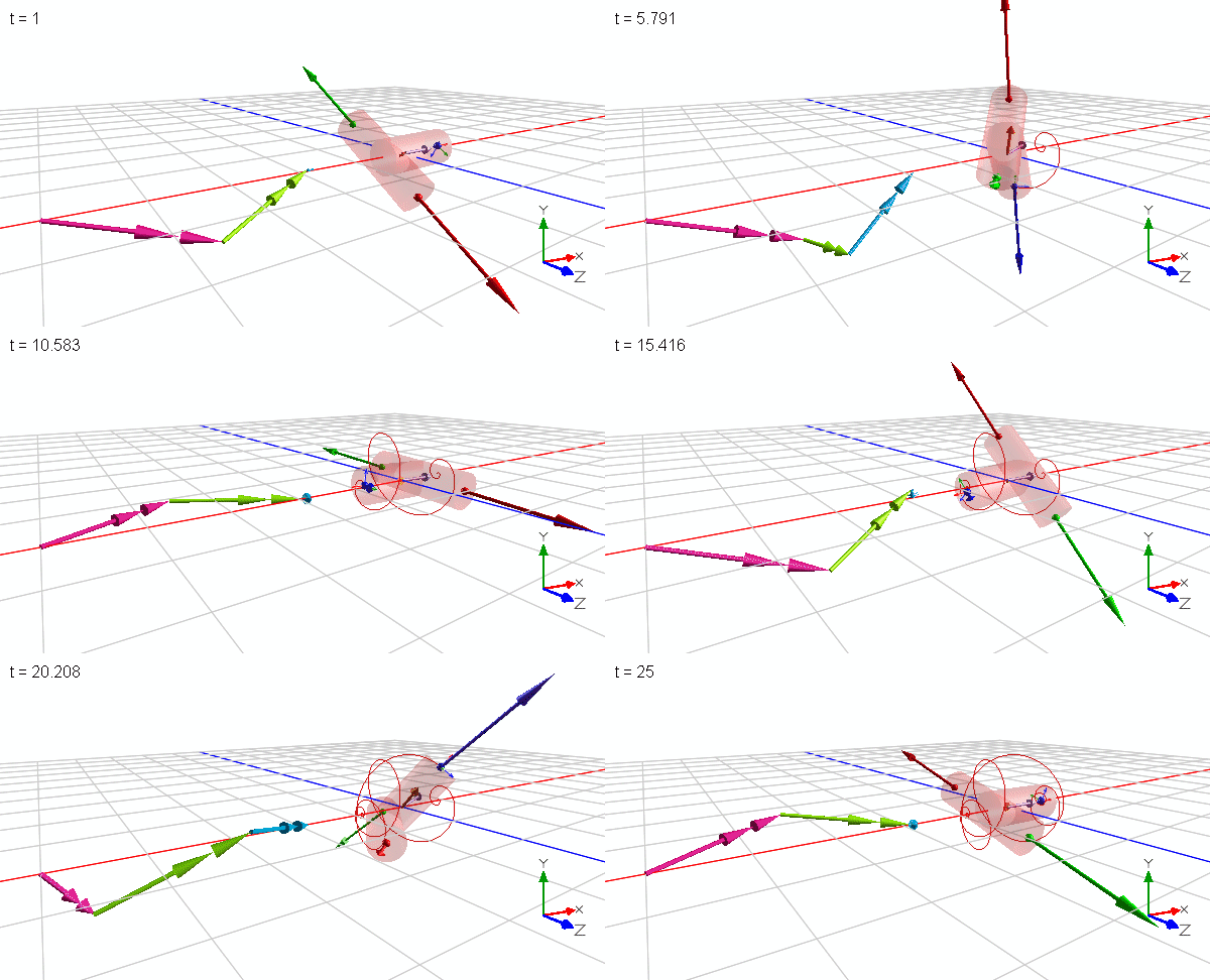
The vector of the angular velocity (violet, at the origin) wobbles during the flip but does not flip direction. The vector of the angular acceleration (orange) rotates in the yz-plane
Forces act in the plane of the triangle. There is no component normal to the plane, as in the YouTube video, that could cause a flip. Thus, the displayed forces measured in the inertial reference frame do not provide an intuitive explanation why the flip occurs.

The same applies for the moments of the forces at the center of mass: They are perfectly balanced. There is no net component that could be attributed to an in-plane rotation.

Why are the animations different: Apparent vs. internal reactive forces.
The MapleSim animation shows internal reactive forces that illustrate the interplay of the moving masses which are bound to each other. They act in the model and obey actio = reactio, which means that the same vectors of opposite sign pull on the masses when the masses are isolated (they follow Newtons second law and equate to mass times the vector of acceleration; the last image in this post displays an isolated mass and the opposing force).
On the contrary, the YouTube animation shows apparent forces (centrifugal forces) that appear when accelerations are described in a reference frame that moves (accelerates or rotates) with respect to the inertial reference frame. They look like external forces acting on the model, but they are not real. Since apparent forces are fictitious (not real), not everyone is satisfied with using them for an intuitive explanation.
Can the MapleSim animation be improved?
Calculation of apparent forces is possible but less straight forward for the simple reason that the Mathematical components library does not provide operators for coordinate transform and matrix multiplication. Those operators are normally not required for simulation purposes. (It would be interesting to see how calcualtion of apparent forces can be done in MapleSim. Verification of code implementation might not be as easy as in the inertial reference frame.)
What ultimately prevents a reproduction of the video is the observer/camera view that rotates with the model. This feature does not exist in the current version of MapleSim 2024. To reproduce the video, Maple has to be used. This would also make the implementation of the calculation of apparent forces much easier as compared to, for example, Modelica code implementation (at least for me).
Is the 3-mass model equally intuitive as a 4-mass model?
The initial idea was to have two orbiting masses that are perturbed by a third mass. The third mass flips like a pointer back and forth while the two masses still follow their orbit. This is in case of 3 identical masses only possible with a short-legged T as shown here:
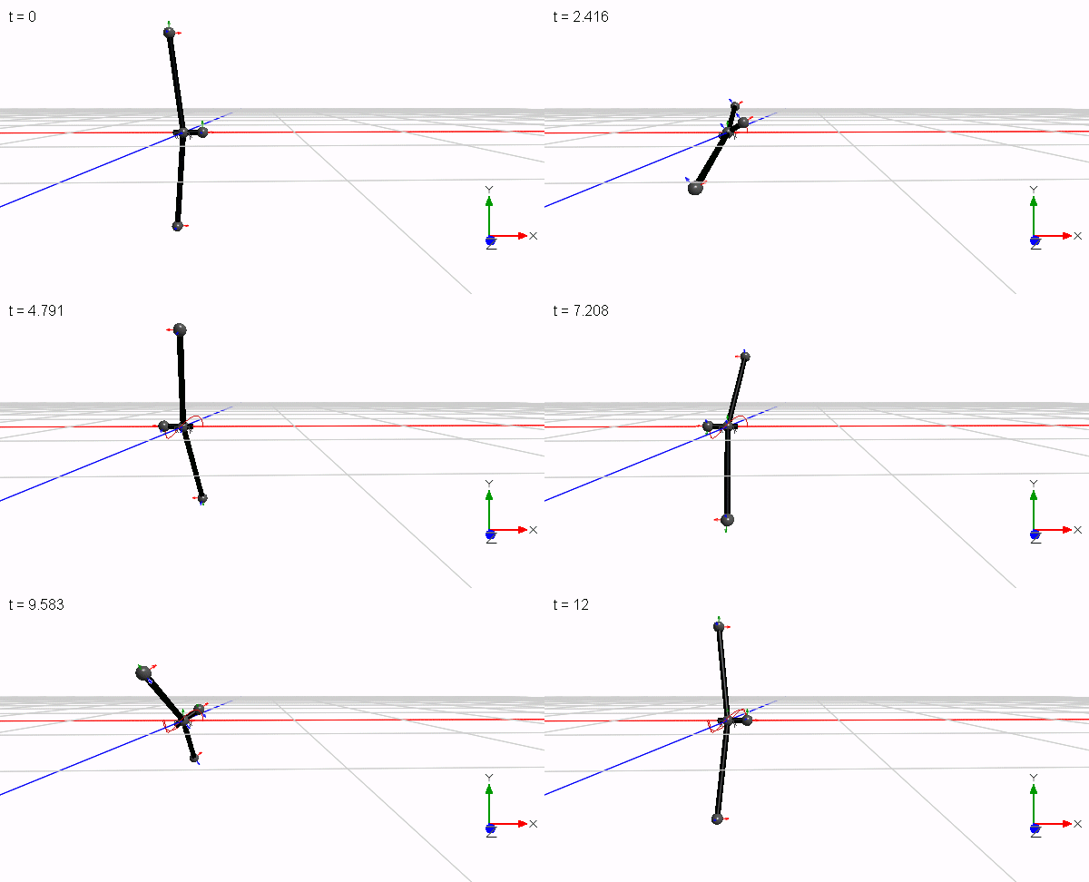
Only a reduced mass would allow for a longer leg. Since the T has only one axis of symmetry, the two orbiting masses do not orbit in a plane. They perform a wobbling motion and shift laterally in position during a flip since the rotation is performed about the common center of mass. Only when 4 masses are used in a symmetrical cross configuration, two masses can orbit closer to a plane that contains the common center of mass while the two perturbing masses flip sides of the plane (the wobble is less pronounced but still visible by the enlarging blue trace in the animation below).
With a mass ratio of 1:100 in the animation below the two orbiting masses create kind of a centrifugal potential field in which the two perturbing masses swing like a pendulum. In this configuration the two perturbing masses can no longer be regarded as strongly disturbing, but rather as oscillating satellites. The sudden flip is created by the increasing accelerating field strength which increases with the distance from the axis of rotation. This lets a pendulum swing with a stronger than expected acceleration and is perhaps a new insight.
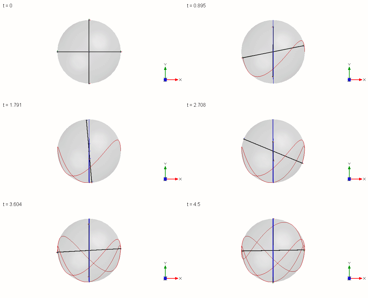
Both models represent the simplest possible implementation to generate the effect in terms of number of parameters. The 4-mass configuration has more objects but is simpler to understand because of the higher degree of symmetry. Either identical masses at varying distances or identical distances at varying masses can be used in both models. No more reduction of parameters is possible to generate the effect. A two mass object cannot even wobble.
Out of plane initial inclination makes the acceptance of an explanation easier since the orbiting masses do not generate a momentum as in the case of an in plane inclination. For the latter case an intuitve explanation is more difficult and perhaps there is none.
Although the pendulum swing of the out of plane case might provide an intuitive explanation of the effect it is not fully satisfying. It does not explain why larger masses than the orbiting masses do not lead to a swing but smaller masses do. Another well-made video provides an explanation for that.
This newer video also gives an explanation why internal forces must act in the plane of the rotating object but does not display them in the animation. I guess this is because the introduction of real forces would have spoiled the intuitive explanation of the video. Isolating a mass and adding an internal force now as an external force leads to an equivalent system that reproduces the effect of the rotating object. If the same force is applied in the opposite direction on the isolated mass, the isolated mass moves along the same trajectory.

4_lumped_masses_and_one_single_force_driven_mass.msim
Isolating only one mass breakes the symmetry of the model. It also gives the false impression that the introduced perturbing force acts primarily on the opposite mass. A 3-mass model does not lead to such a false interpretation. By isolating the opposite mass and introducing a second perturbing force, the discussion shifts more to the analysis of the wobble and the rotational acceleration of the orbiting masses and less to the flip.
In summary, internal forces describe how the masses interact but their orientation is counterintuitively perpendicular to direction of the flip. On the other hand, centrifugal forces that we intuitively assume acting in a 4-mass model from the perspective of an observer from an inertial reference frame do not exist. This assumption provides an intuitive explanation which is physically wrong. In the same way an accelerating radial force field does not exist. Mathematically and physically correct is a description from a rotating observer which uses fictious forces.
For me both intuitive explanations of the videos are somehow useable, but both involve centrifugal forces (in one case explicitly and in the other wrongly assumed by an observer). This is not satisfying when the goal is not to use fictious forces.
Conclusion
MapleSim visualization components can be used for more than displaying forces and moments. They are very helpful to better understand physical phenomena.
A camera view observer on a rotating reference frame would have made observation of the direction of the internal forces much easier and might have given more insights. As of now, Maple is required to reproduce the animation in the video.
There is no better intuitive visualization/explanation with a model of 3 identical masses. A 4-mass configuration provides better insight but does not explain all.
In reality every freely rotating object with more than two point masses inevitably wobbles.